

Features
Top in its class with three dynamic ranges.
Alive and well, the non-tiring KENWOOD tone keeps you listening.
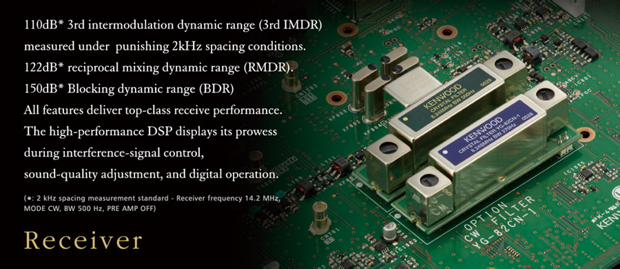
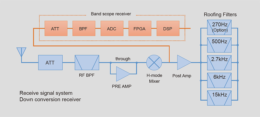
Receive performance on a whole other level from narrow bandwidth roofing filters that only full down conversion can provide
The TS-890S uses 8.248MHz 1st IF frequency down conversion for its receive signal system in order to continue the adjacent interference signal exclusion legacy refined in the TS-990S. This means you can use narrow bandwidth crystal filters with passband widths of 500Hz or 270Hz (optional YG-82CN-1) as roofing filters to achieve strong exclusion of unnecessary adjacent signals. The 1st mixer is the H-mode mixer also carried by the TS-990S. Conversion characteristics have been improved with fine-tuning of input/output matching as well the device used.
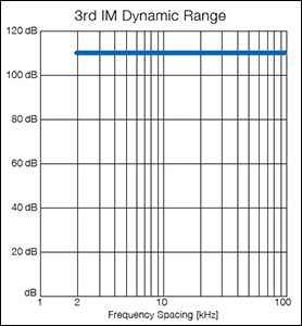
3rd intermodulation dynamic range
(3rd IMDR)
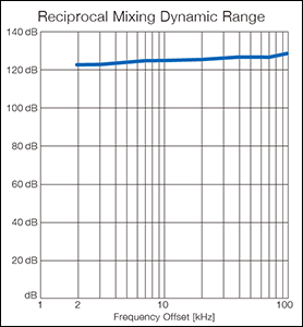
Reciprocal mixing dynamic range
(RMDR)
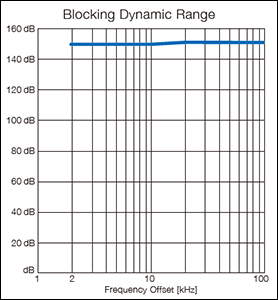
Blocking dynamic range
(BDR)
Measurement conditions (shared) Frx=14.2 MHz, PRE AMP OFF, BW 500 Hz, CW
Vertical axis: Dynamic range (shared)
Horizontal axis: Interference signal interval (3rd IMDR), interference signal isolation frequency (RMDR, BDR)
・Values are measured examples.
High-speed scanning with independent band scope receiver
The configuration of the band scope receiver has changed from the superheterodyne system used in the TS-990S to 1st IF sampling using an A/D converter (14bit/39MHz), and FPGA digital down conversion. This means a change in scanning method from step FFT to FFT, achieving highspeed updates to the display irrespective of span settings.
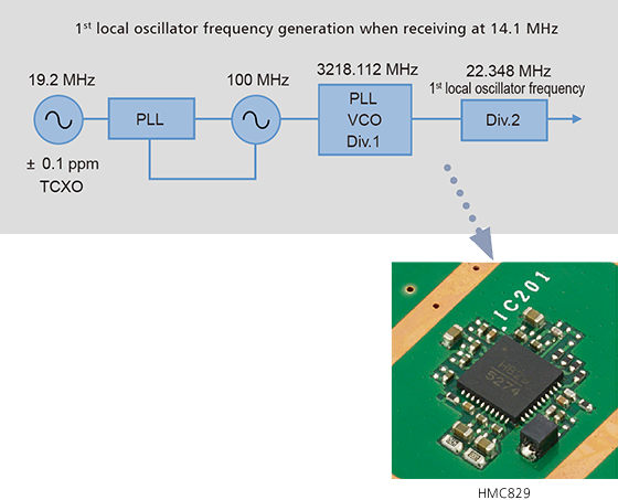
Local oscillator realizes superior C/N
Interference signal exclusion is not determined by roofing filters and signal system devices alone. The TS-890S has taken the VCO division of the TS-990S and developed it further, combining a VCO device with high C/N in the gigahertz band and a reference oscillation circuit with superior adjacent C/N to deliver C/N characteristics unattainable in conventional units.
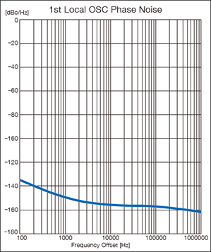
1st Local OSC Phase Noise (14.1MHz)
・Values are measured examples.
The speed and quality of KENWOOD’s renowned IF AGC control
A variety of functions are realized through 32-bit floating-point DSP technology inherited from the TS-990S, including modulation/demodulation in all modes, IF filter, IF-AGC, and removal of interfering signals. Popular for its non-tiring and great-quality audio, the IF-AGC has undergone a facelift with a combination of roofing filters and IF filters, and has been designed to enable optimal control under various noise circumstances.
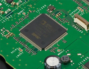
For IF DSP, transmitter
ADSP-21363 clock @332MHz
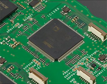
For band scope
ADSP-21363 clock @332MHz
Other receiver system features
- ● RF ATT(OFF/6/12/18dB)
- ● Preamp(PRE1/PRE2)
- ● Receive only antenna connector(RX IN, RX OUT)
- ● Antenna output connector
Specification
| General | ||
|---|---|---|
| Frequency range (Transmitter) |
160m band | 1.81 ~ 2.0 MHz |
| 80m band | 3.5 ~ 4.0 MHz | |
| 60m band *1 | 5.1675 MHz, 5.25 ~ 5.45 MHz | |
| 40m band | 7.0 ~ 7.3 MHz | |
| 30m band | 10.1 ~ 10.15 MHz | |
| 20m band | 14.0 ~ 14.35 MHz | |
| 17m band | 18.068 ~ 18.168 MHz | |
| 15m band | 21.0 ~ 21.45 MHz | |
| 12m band | 24.89 ~ 24.99 MHz | |
| 10m band | 28.0 ~ 29.7 MHz | |
| 6m band | 50.0 ~ 54.0 MHz | |
| Frequency range (Receiver) | 0.13 ~ 30 MHz, 50 ~ 54 MHz, VFO: Continuous 30 kHz ~ 60 MHz |
|
| Mode | A1A(CW), A3E(AM), J3E(SSB), F1B(FSK), F3E(FM), G1B(PSK) | |
| Frequency stability | ±0.1 ppm, +32 °F ~ +122 °F (0 °C ~ +50 °C) | |
| Antenna impedance | 50 Ω | |
| Antenna tuner load range | 16.7 Ω ~ 150 Ω | |
| Supply voltage | DC 13.8 V ±15 % | |
| Ground | Negative ground | |
| Current Drain | TX | 22.5 A or less |
| RX (No signal) | 2.5 A or less | |
| Operating Temperature | +32°F ~ +122 °F (0 °C ~ +50 °C) | |
| Dimensions | Without projections | W15.59 x H5.56 x D13.38 in. (W396.0 × H141.3 × D340.0 mm) |
| With projections | W16.13 x H6.23 x D15.25 in. (W409.6 × H158.3 × D387.4 mm) | |
| Weight | Approx. 34.8 lbs (15.8 kg) | |
| Transmitter | ||
|---|---|---|
| Output Power (AM) | Max 100 W / Min 5 W, (Max 25 W / Min 5 W) | |
| Modulation | SSB: Balanced, AM: Low Power, FM: Reactance | |
| Maximum frequency deviation (FM) | wide: ±5 kHz or less, narrow: ±2.5 kHz or less | |
| Spurious emissions | HF: -50 dB or less | |
| 50 MHz: -60 dB or less | ||
| Carrier suppression | 60 dB or more | |
| Unwanted sideband suppression | 60 dB or more | |
| Transmit frequency response | Within -6 dB (100 ~ 2,900 Hz) | |
| Microphone impedance | 600 Ω | |
| XIT variable range | ±9.999 kHz | |
| Receiver | ||
|---|---|---|
| Circuit type | Double Superheterodyne | |
| Intermediate frequency | 1st IF | 8.248 MHz |
| 2nd IF | 24 kHz / 36kHz (FM) | |
| Sensitivity (TYP) |
SSB / CW / FSK / PSK (S/N 10 dB) |
0.5 μV (0.13 ~ 0.522 MHz) |
| 4 μV (0.522 ~ 1.705 MHz) | ||
| 0.2 μV (1.705 ~ 24.5 MHz) | ||
| 0.13 μV (24.5 ~ 30 MHz) | ||
| 0.13 μV (50 ~ 54 MHz) | ||
| AM (S/N 10 dB) | 6.3 μV (0.13 ~ 0.522 MHz) | |
| 31.6 μV (0.522 ~ 1.705 MHz) | ||
| 2 μV (1.705 ~ 24.5 MHz) | ||
| 1.3 μV (24.5 ~ 30 MHz) | ||
| 1.3 μV (50 ~ 54 MHz) | ||
| FM (12 dB SINAD) | 0.22 μV (28 ~ 30 MHz) | |
| 0.22 μV or less (50 ~ 54 MHz) | ||
| Squelch Sensitivity | SSB / CW / FSK / AM | 5.6 μV or less (0.13 ~ 0.522 MHz) |
| 18 μV or less (0.522 ~ 1.705 MHz) | ||
| 1.8 μV or less (1.705 ~ 30 MHz) | ||
| 1.1 μV or less (50 ~ 54 MHz) | ||
| FM | 0.2 μV or less (28 ~ 30 MHz) | |
| 0.2 μV or less (50 ~ 54 MHz) | ||
| Image Rejection Ratio | HF:70 dB or more, 50 MHz: 60 dB or more | |
| IF Rejection Ratio | 70 dB or more | |
| Selectivity | SSB | 2.6 kHz or more (-6 dB) |
| 4.4 kHz or less (-60 dB) | ||
| CW / FSK | 500 Hz or more (-6 dB) | |
| 1.2 kHz or less (-60 dB) | ||
| AM | 6.0 kHz or more (-6 dB) | |
| 12 kHz or less (-50 dB) | ||
| FM | 12 kHz or more (-6 dB) | |
| 25 kHz or less (-50 dB) | ||
| RIT variable range | ±9.999 kHz | |
| Notch filter attenuation | 60 dB or more (Auto), 70 dB or more (Manual) | |
| Beat cancel attenuation | 40 dB or more | |
| Audio output | 1.5 W or more (8 Ω) | |
| Audio output impedance | 4 Ω ~ 8 Ω | |
● Supplied accessories
- ■ DC power cord x1
- ■ 7pin DIN Plug (For REMOTE connector x1)
- ■ 13pin DIN Plug (For ACC2 connector x1)
- ■ Spare Fuse 4A x1
- ■ Spare Fuse 25A x1
- ■ Operation Manual x1
- ■ Warranty Card x1
KENWOOD SKY COMMAND SYSTEM II is a registered trademark of JVC KENWOOD Corporation in the U.S.
*1 60 m band: Refer to applicable Amateur Radio regulations to your country.
Electronic specifications apply only to amateur bands. Receive sensitivity drops in the vicinity of the 1st IF frequency (8.248MHz) due to IF trapping.
Internal beat may occur during amateur band receive. Band scope (waterfall) screen may also display spurious signals other than receive signal.


Reviews
There are no reviews yet.